
Pre-Planning Investigations for nbn Fixed Wireless
After reading about the experiences of others with Fixed Wireless NBN non-standard installations on BIRRR and the Whirlpool Forums, I began investigating our own non-standard installation. The main challenge being that a corner of the property was included in the fixed wireless coverage however the house was located approximately 6 kilometres away with no direct line of sight. Further to this, the location where I wanted to install the NBN FW receive station was outside of the NBN FW coverage map despite having direct line-of- sight to the NBN tower. I provided the RSP with the
following:
The direct line-of- sight photograph 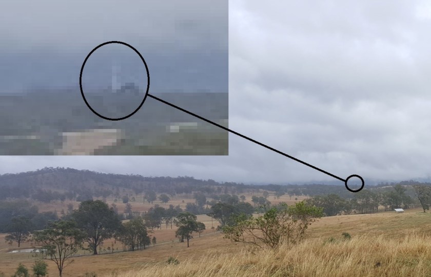
A Ligowave link simulation report including all required parameters (including not being centred within the sector on a tower that did not have 360 degree coverage).
A mock-up of the enclosure for the FW NTD

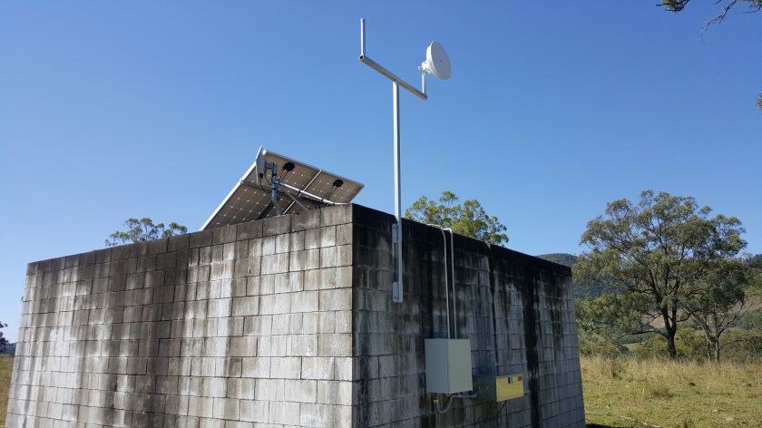
Some possible structures that it could be installed (old unused water tank, old cottage, etc) and the installation address.
The installation was accepted, and the real work commenced.
Installation – FW NBN Receive Station
A day before the scheduled installation, the installer phoned to confirm directions and I took the opportunity to ask what he knew about non-standard installations, “never heard of them” was the response. I briefly explained the situation and he agreed to come and check it out. I also printed out a heap of examples and information, mostly from the BIRRR website just in case some non-standard installation education was required (in the end it wasn’t).
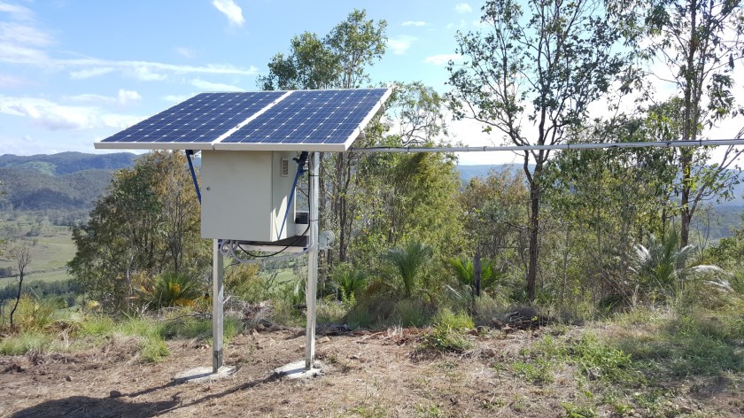
I arrived on-site before the NBN installer and rolled out my Version 1 equipment/install.
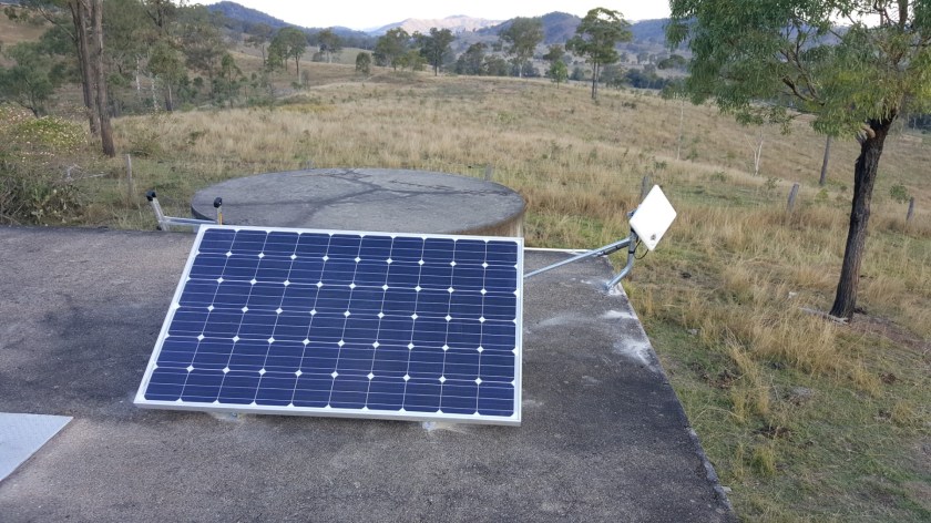
- 250W panel (second hand grid connect panel).
- 12V lead acid battery – 100Ah AGM; mounted inside a cheap Bunnings toolbox mounted to the wall using some Bunnings L-brackets.
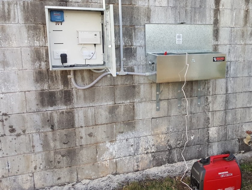
- A weatherproof enclosure housing:
- Victron 75/15 MPPT charge controller (for charging battery).
- 12V to 240V inverter (Supercheap Auto – not visible in photo 1 as it is behind the
panel and wired to the 240V GPO). - The router.
- And of course, space for the NBN’s FW NTD.
The installer arrived and long story short:
- Installer looked at the site and said it met all of the NBNCo’s requirements (power,
weatherproof, to a structure). I know there is a lot of conjecture about exactly what these
requirements actually are and I recognise his information may not be the NBN policy
(whatever it is) but as he was the (sub) contracted representative his opinion was good
enough for me. No need to give him the printed BIRRR examples. - Installer performed a signal test and he was somehow picking up two sectors.
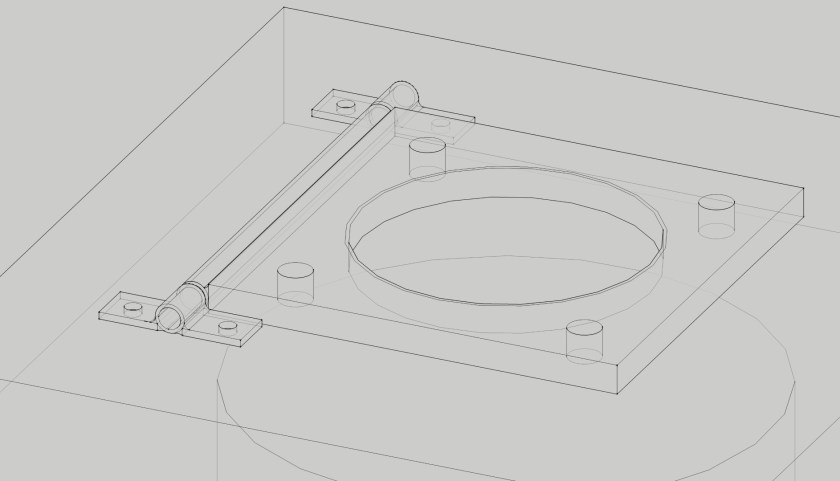
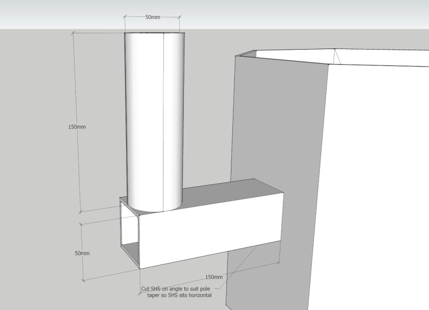
- Installer would not install the ODU onto my custom T-pole mount (see pictures) without first getting approval from Ericsson but said he could proceed with using the standard mount right away (the latter option was gladly taken!).
- The NBN FW was completed and as it turns out; this was the easiest part getting our NBNFW!
PtP Relay Station (and UHF repeater)
An intermediate relay station would be placed centrally and elevated on the property with line of sight to both the NBN FW Receive Station and the House. It was also decided that this site would a house private UHF radio repeater.


The following items were sourced:
- 15m lighting tower sourced from Gumtree.
 Modifications were made to it including a base pivot point, 2x mounting points for the Ubiquiti radios at 8m elevation, and a UHF antenna mount at the 15m elevation.
- A weatherproof enclosure (second hand) for housing the electrical and communications equipment.
- A fabricated steel frame which would support the enclosure above, the solar panels and a toolbox (Masters liquidation special) to house the battery.
The tower foundation was installed using a 600mm auger with rock struck at 0.75m depth. Jackhammer was used to dig a further 0.75m; resulting in a total depth of 1.5m (of which 0.75m was into a 0.75m very strong, non-weathered rock). A rebar cage with anchor bolt template was placed into position and 0.5m 3 (1.2T) of 40MPa concrete was hand-mixed and placed. Because of the swing mechanism of the tower, the threaded rod anchors could not extend above the finished concrete level. The anchor bolt assembly and template was made up of 4x M24 Gr8.8 galvanised threaded rod terminated into M24 Hex Couplers with a ply spacer/template to set positions. 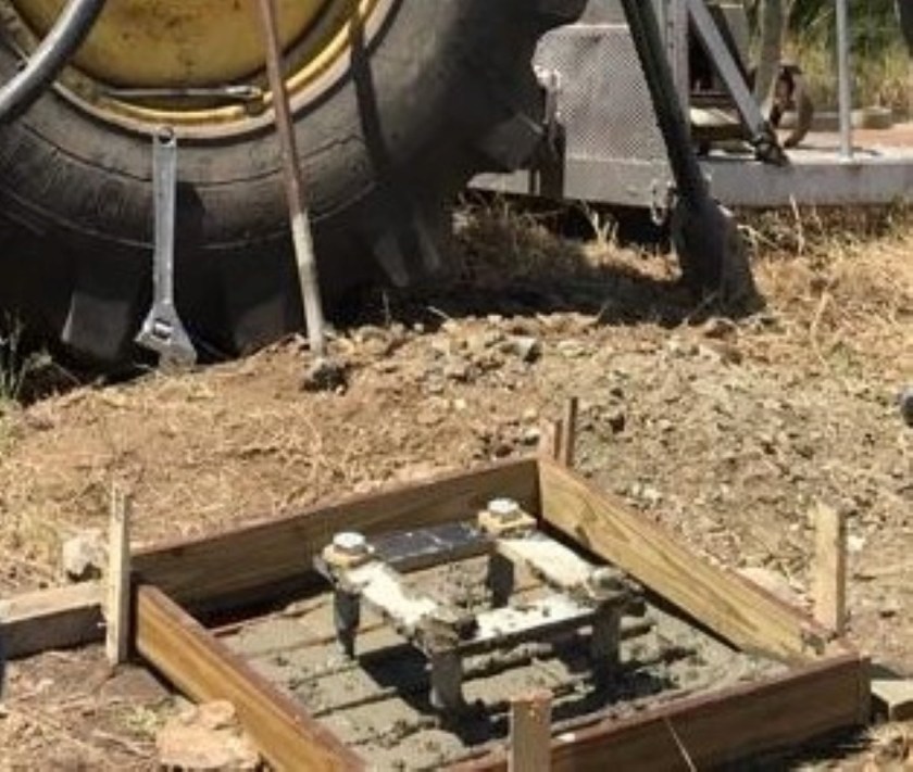 The equipment enclosure steel frame was also concreted into position.
A month later we returned to erect the tower. Equipment (details below) and cables were installed on the ground. 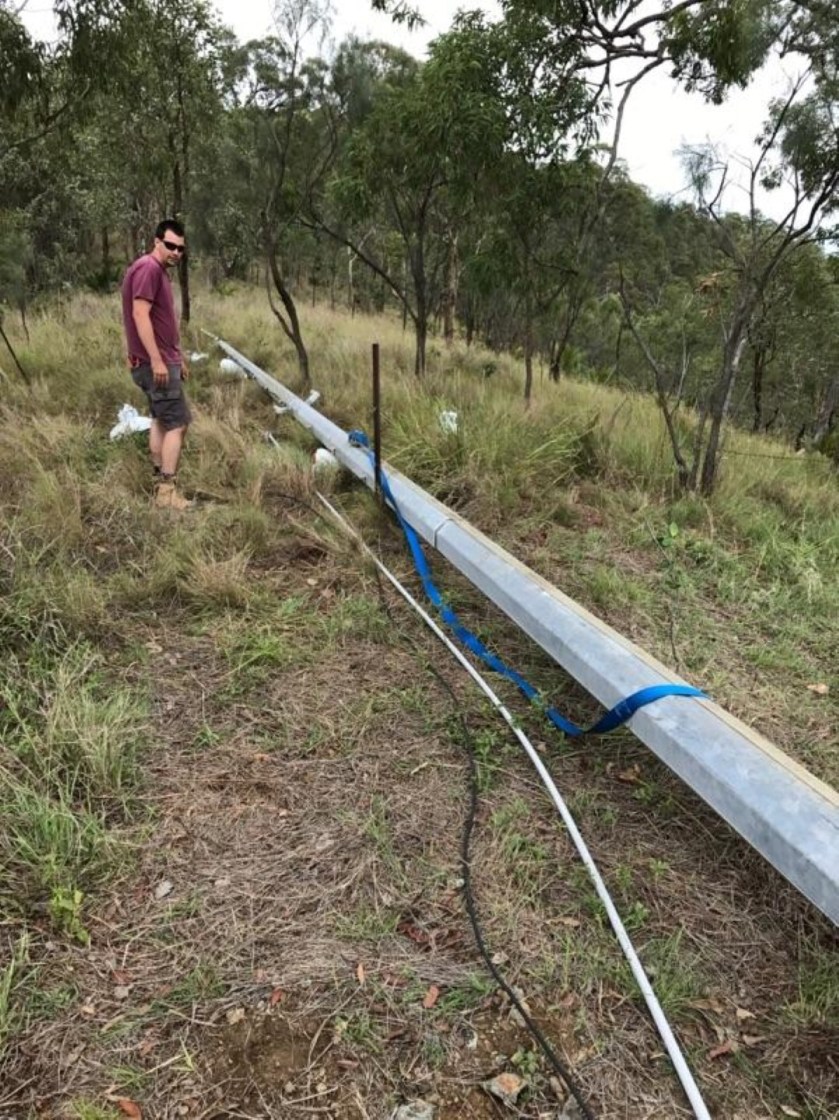 Concrete screws (Ramset Ankascrew) were used to pin the base plate hinges to the foundation and the tower was then raised.
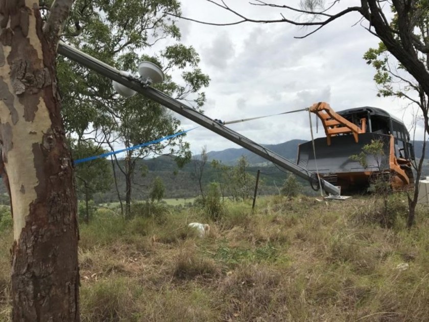

Once raised, a few taps of a sledge hammer positioned the base plate holes precisely over the embedded hex couplers female threads, and the M24 bolts were installed securing the upright tower.
The following equipment was fitted out on the tower and enclosures:
- 2x Ubiquiti Powerbeam M5 400 radios (with ISO reflectors but these are probably
unnecessary). - 1x Ubiquiti ToughSwitch POE. This is powered directly from the battery output and the
Powerbeam/Toughswitch are not adversely affected by being powered directly from the 12V battery (which in practice fluctuates from 12.6V – 14.6V depending on the charge state). - 1x 12V lead acid battery – 300Ah AGM. As this battery weighs 76kg, a hand winch and swing arm were also installed to the enclosure mounting frame to make removal and replacement easier.
- 2x 250W solar panels (grid-connect type). Ample power generation capacity with a
philosophy that this would provide sufficient power to recharge the battery to 100% even on the cloudiest of days. - 1x Victron 100/30 MPPT Charge Controller – for charging battery.
- 1x Raspberry Pi 2 with Victron’s Venus GX software installed to remotely monitor the Victron charge controller and provide live battery voltage status. This was powered by a USB Charger.
- Cooling fan and LED strip lights were also installed within the enclosure.
- As the site also includes a UHF repeater – the receive radio, transmit radio and UHF duplexer were also installed.
- Ubiquiti Surge Protectors were installed for the Powerbeams.
 - Copy")
 - Copy")


Upgrade of NBN FW Receive Station for PtPtP usage
An Ubiquiti Powerbeam M5 400 was installed and mounted to the T-pole mount I had fabricated. An additional 250W solar panel was added as I felt I may have undersized the 12V battery (only 100Ah). By adding this panel, I ensured that even on the cloudiest of days, the battery is still reaching 100% charge. The 12V-240V inverter was removed and replaced with a Victron 12/12 DC- DC Converter to power the NBN FW NTD providing a regulated constant 12V output even when the voltage from the battery fluctuates from 12V-15V (as the charge state varies).
A cheap Netgear WNDR2000v5 router (which is also powered by the Victron 12/12) has been added since the photos were taken. This was done to separate the routing hardware, make remote web- based management simpler and resulted in improved network performance.
using it)


Battery enclosure & Inside enclosure.
Tips & Lessons Learned
Some tips based on my experience (some are pretty obvious but caught me out):
- When you have 2x Ubiquitis at the same location (even if they are pointing in completely different directions with ISO reflectors), ensure you manually assign the link channel so that no part of the frequency overlaps with that of the adjacent radio (e.g. a 5800Mhz with 40Mhz will spread from 5780-5820Mhz so the adjacent radio would need to be set at 5840Mhz). Using the AUTO channel setting will not achieve the required separation.
- On the rare occasion, the Ubiquiti radios go non-responsive and require a power reset;
which is an inconvenience for remote installations. Fortunately the software on the Ubiquiti radio (AirOS) and ToughSwitch (EdgeOS) include a Watchdog feature which allows the radio to send a ping to an IP address and if no reply is received after a certain period of time, the radio will reset itself. In the case of the ToughSwitch, the power will be removed from the POE port forcing a power cycle reset of the connected radio. - Remote monitoring and control feature has been installed to make fault finding very
efficient (most of the time it can be done remotely). The Ubiquiti Network Management
System (UNMS) has been installed which provides internet based monitoring (so the system can be seen from both the house side and the internet side.
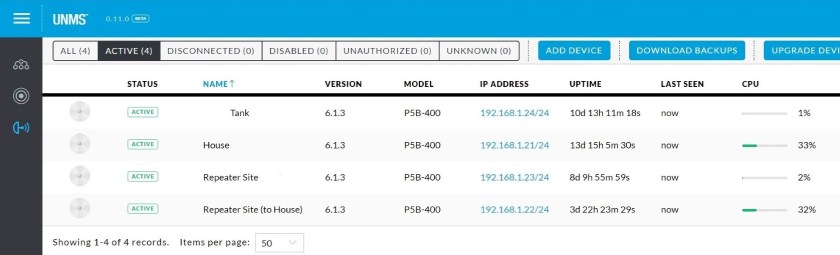
dashboard
Web-based remote management (with Dynamic DNS) has been enabled for the
Router and ToughSwitch (using port forwarding) allowing further web-based monitoring and control.

Victron data is uploaded to Victron’s VRM servers allowing live and historic data of the solar charge controller and battery voltage.
I used lead acid AGM batteries and these can provide a reasonably long service life providing you do only discharge to about 20% depth of discharge. When these reach the end of their life, I will likely replace with LiFePO4 type 12V battery. These allow you to discharge much more deeply therefore you can use a smaller, lighter and less total capacity battery while achieving the equivalent usable capacity. Although they have a higher upfront cost, I suspect the lifetime cost will be less (but if you do this don’t forget to edit the charge controller settings to suit the battery type). When the time comes for replacement I will do some more precise power usage measurements with a shunt and size accordingly. Based on the data collected from the charger/voltage monitoring I’m using about 30Ah overnight at the Relay Station. I would estimate that the NBN FW station uses about 20Ah overnight. The 500W of solar at each site would have no have no trouble returning these to 100% every day.
Conclusion
This turned out to be a much bigger job than originally anticipated. Everything was that little more difficult because the hill relay site was very steep only accessible by ATV and large tractor/bulldozer.
The overall cost was approximately $8,000 for equipment and materials; and this figure does not include labour or plant (which fortunately for us was no cost). The end result is a low latency connection getting 43 Mbps down & 17 Mbps up.

Unfortunately there is some congestion impacting us at either the RSP or NBN level, which depending on the time of day will range between 20-38 Mbps. Nevertheless, it is a drastic improvement over the previously connected IPstar satellite system and hopefully it proves to be a reliable network connection well into the future.
Disclaimer: This document is meant as an informative document based on my own research and experience. Any views, opinions, information etc. provided is not necessarily the same as that provided by NBN Co, BIRRR, or any other organisation referred to here. Prepared for BIRRR by Jostin Meekels.
